HEIM / Nachricht / Referenzhandbuch für den Mindestbiegeradius des Zahnriemens AT10 und die Größe der Umlenkrolle
Nachricht
Referenzhandbuch für den Mindestbiegeradius des Zahnriemens AT10 und die Größe der Umlenkrolle
Angenommen, Sie legen einen AT10-Zahnriemenantrieb in einer Verpackungsmaschine aus und die Zeichnung sieht nur 55 mm Platz für eine Umlenkrolle vor. Eine 50-mm-Leitrolle mit glatter Rückseite scheint zu passen, aber wenn die Spannrolle stattdessen auf den Riemenzähnen läuft, wird die gleiche Stelle zu einem Fehler, der nur darauf wartet, passiert zu werden. Der Riemen muss sich um einen Mindestradius biegen, und die Größe der Umlenkrolle ist das Maß, das diesen Radius erzeugt. In practical terms, an AT10 belt with steel tension cords should not be wrapped over an idler smaller than 50 mm on the smooth back, and not smaller than 120 mm when running on the teeth. Diese Werte sind kein Luxus: Sie schützen die Zugträger und den Zahn-Seil-Verbund vor vorzeitiger Ermüdung. This guide walks you through the reasoning, the typical numbers, and how to apply them in a real drive.
Grundlagen des AT10-Profils und des minimalen Biegeradius
AT10 is a 10 mm pitch trapezoidal timing belt profile commonly used in industrial drives that need accurate indexing, repeatable positioning, and moderate power transmission. Die Teilungslinie ist der gedachte Kreis innerhalb des Riemens, in dem die Zugstränge verlaufen. When the belt bends around a pulley or idler, the cord layer is forced to accommodate the difference between the outer and inner surfaces of the bend. Wenn der Biegeradius zu eng ist, unterliegen die Stahlseile bei jedem Durchgang durch dieses Element einer hohen Wechselbelastung.
Der minimale Biegeradius ist leichter zu verstehen, wenn man an eine einfache Umlenkrolle denkt. Eine zylindrische Spannrolle erzeugt einen Biegeradius, der etwa der Hälfte des Spannrollendurchmessers entspricht. A 50 mm smooth-back idler produces a 25 mm bend radius, while a 120 mm tooth-side idler produces a 60 mm bend radius. Die tooth-side value is larger because the belt tooth root and the cord bond are more sensitive to flexing and pinch forces than the smooth back surface.
Dieses Liniendiagramm zeigt den Zusammenhang zwischen Rollendurchmesser und Biegebelastung der Spannstränge. The curve drops steeply in the 20 to 60 mm range, which means small pinions and idlers create a big fatigue penalty. Above 100 mm the curve becomes flatter, so an AT10 tooth-side idler at 120 mm is already on the safe plateau. If you reduce the idler from 50 mm to 40 mm, the increase in strain is much larger than the change in envelope size suggests. That is why manufacturer tables specify a minimum idler diameter and why experienced designers treat it as a strict limit. A line chart is a good way to explain the fatigue trade-off to a machine builder before the prototype is cut.
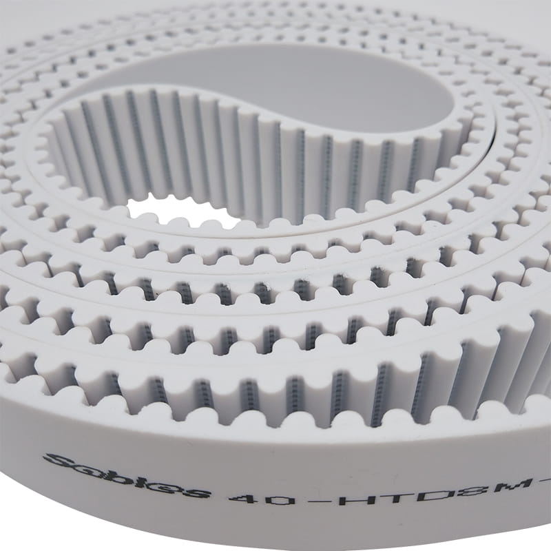
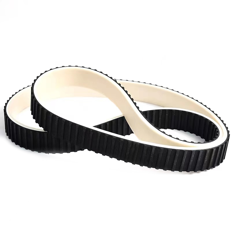
Viele AT10-Riemen werden aus gegossenem Polyurethan hergestellt, da das Material abriebfest ist und sein Zahnprofil bei wiederholter Biegung beibehält. For drives that need that combination of properties, a polyurethane AT10 belt is a common starting point.
When you choose a polymer body, confirm that the supplier minimum idler values match your cord specification, because the cord is the part that actually sets the bend limit.
Referenzwerte für die AT10-Umlenkrollengröße
Most AT10 design tables list three numbers: minimum pulley teeth, minimum idler diameter on the smooth back, and minimum idler diameter on the belt teeth. The values below reflect standard steel-cord AT10 belts used in industrial drives. Sie sind ein sicherer Ausgangspunkt, ersetzen aber kein herstellerspezifisches Datenblatt.
Typische Mindestkonstruktionswerte für Standard-Stahlcord-AT10-Zahnriemen. Bestätigen Sie die Werte mit dem Riemenlieferanten, bevor Sie ein Antriebslayout festlegen.
Parameter
Mindestwert
Praktischer Hinweis
Minimale Riemenscheibenzähne
15
Ergibt einen Schlagkreisdurchmesser von etwa 48 mm.
Mindestdurchmesser der glatten Spannrolle
50 mm
Wird verwendet, wenn eine Spannrolle die Außenfläche berührt.
Mindestdurchmesser der zahnseitigen Spannrolle
120 mm
Wird verwendet, wenn eine Spannrolle die Riemenzähne berührt.
Mindestbiegeradius auf glatter Rückseite
25 mm
Ungefähr die Hälfte des 50-mm-Rollendurchmessers.
Mindestbiegeradius auf der Zahnseite
60 mm
Ungefähr die Hälfte des 120-mm-Rollendurchmessers.
The horizontal bar chart makes it easy to compare the three diameter limits that will fit under the hood of most machines. Beachten Sie, dass die Antriebsriemenscheibe mit 15 Zähnen nur geringfügig kleiner ist als die 50-mm-Grenze für die Spannrolle mit glatter Rückseite. The tooth-side idler is the largest restriction, so it is usually the dimension that determines whether a belt path can fit into a compact housing. If your layout passes the tooth-side idler check, the smooth-back idler and pulley are often already acceptable. This is why engineers are told to draw the entire belt path, including idlers, before ordering pulleys. The 120 mm bar is not an arbitrary safety factor; it represents the point where the belt tooth profile and cord bond have a reasonable margin.
Was passiert, wenn der Biegeradius zu klein ist?
Wenn ein AT10-Riemen um einen Radius gezwungen wird, der kleiner als der Mindestradius ist, sind die ersten Anzeichen einer Beschädigung oft nicht auf der Riemenoberfläche sichtbar. The steel cords inside begin to work-harden and crack from the inside as they are flexed repeatedly over a sharp curve. Gleichzeitig verbiegt sich der Zahnfuß des Riemens stark und kann sich an der Basis öffnen. Der Riemen läuft möglicherweise auch etwas anders auf der Spannrolle und erzeugt Geräusche und Vibrationen, die den Riemenscheibenflansch langsam verschleißen. In a production machine, the usual result is a belt that looks healthy on a Friday and then snaps, skips teeth, or delaminates at the worst possible moment.
This column chart compares the relative flex life of an AT10 belt under three idler scenarios. Eine Unterdimensionierung der zahnseitigen Umlenkrolle um 20 mm kann die Lebensdauer des Riemens im Vergleich zu einer großzügigen Auslegung um fast die Hälfte verkürzen. Wenn die Spannrolle genau auf dem Mindestwert gehalten wird, ergibt sich eine akzeptable Lebensdauer, es besteht jedoch wenig Spielraum für Abweichungen oder Fehlausrichtungen der Riemenlänge. Eine Überdimensionierung der Spannrolle um 20 Prozent kostet etwas Platz, bringt aber eine viel größere Sicherheitsmarge mit sich. The chart also explains why experienced machine builders do not try to save 5 mm of envelope space by reducing an idler from 120 mm to 100 mm. The life difference is too large to justify the small gain in packaging.
Regeln für Größe und Platzierung der Umlenkrolle
Once you know the minimum diameter, choose the idler bearing and pulley material carefully. An idler that runs on the belt back should be smooth and slightly crowned to help track the belt without adding friction. Eine Spannrolle, die auf den Riemenzähnen läuft, sollte ein Profil verwenden, das auf die AT10-Zahngeometrie abgestimmt ist; Eine flache Spannrolle auf den Zähnen kann die Zahntaschen einklemmen und den Verschleiß beschleunigen. A common rule of thumb is to make the smooth-back idler diameter at least equal to the drive pulley pitch diameter, which for a 15-tooth AT10 pulley means about 50 mm.
Smooth-back idler: minimum 50 mm diameter, with a crowned or flat face depending on belt width.
Tooth-side idler: minimum 120 mm diameter, with an AT10-compatible tooth profile.
Place the idler on the slack span whenever possible so it does not add unnecessary load to the tight side of the drive.
Avoid placing an idler immediately at the entry point of a small pulley, because the combined bend can exceed the material limit.
Überprüfen Sie die Kombination aus Riemenscheibenflanschhöhe und Riemenbreite, um Kantenverschleiß und Probleme mit der Spurführung zu vermeiden.
Idler position is just as important as idler size. A correctly sized idler in the wrong position can create excessive belt preload, increase bearing load, or force the belt into an S-shaped path. Keep the wraps as clean as possible and give the belt enough straight span between pulleys for the flex to recover.
AT10-Materialauswahl und ihr Einfluss auf die Biegegrenzen
AT10 belts are available in different body materials, and the body compound affects tooth rigidity, abrasion resistance, and heat tolerance. Für einen minimalen Biegeradius ist jedoch der Zugstrang das wichtigste steuernde Element. A steel-cord belt will behave differently from a glass-cord belt even when the tooth profile is identical. The body material still matters because it determines whether the tooth root can survive repeated flexing without cracking.
The radar chart is a useful way to compare the general characteristics of rubber and polyurethane AT10 belt constructions. Polyurethane usually shows higher abrasion resistance and more rigid teeth, which helps in dirty or high-torque positioning drives. Rubber belts often give better heat resistance and a quieter engagement in lower-speed applications. For minimum bend radius, the cord material matters more than the body compound, because both constructions rely on steel or glass tension members. Therefore, you should not choose a rubber belt simply because it feels more flexible when the limiting factor is still the cord. Use this chart as a selection checklist and then confirm the final choice with the supplier flex-fatigue data.
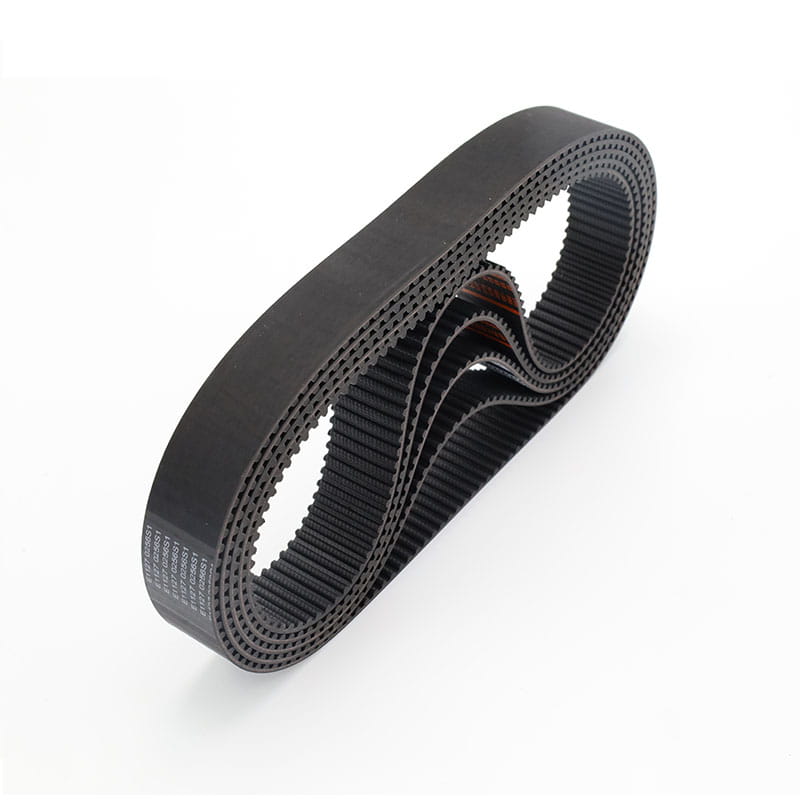
For equipment running in hot environments or where vibration damping is important, a rubber timing belt can be a practical alternative to polyurethane. The same minimum pulley and idler rules still apply, but the supplier should verify the exact values for the chosen rubber compound.
In both cases, request test reports that show flex fatigue under dynamic load rather than only static tensile strength.
Abschließende Designprüfungen und Installationshinweise
Once the belt path is drawn on paper or in CAD, run through a short checklist before ordering parts. The AT10 minimum bend radius is not a hidden spec reserved for engineering specialists, but it must be checked at every wrapped element in the drive.
Verify that every pulley and idler meets the AT10 minimum tooth count and diameter limits.
Confirm whether each idler contacts the smooth back or the belt teeth, and apply the correct minimum value.
Keep the minimum bend radius at least 25 mm on the smooth back and at least 60 mm on the belt teeth.
Place tensioners and idlers on the slack span whenever possible to reduce the additional load on the belt.
Check the pulley flange height, belt width, and center distance before finalizing the design.
A few millimeters of idler diameter are much cheaper than an unscheduled line stop. Select at least 15 pulley teeth, a 50 mm smooth-back idler, and a 120 mm tooth-side idler for standard steel-cord AT10 belts. Starting with these numbers puts the drive on the safe side, and verifying the values with a manufacturer datasheet gives the final engineering confidence.
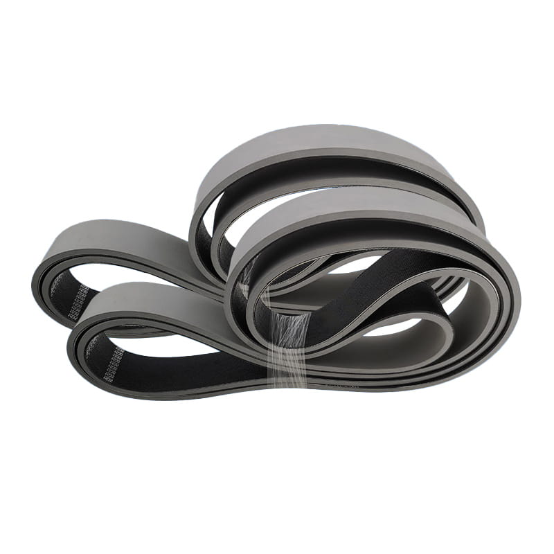
Der Weitwinkelriemen ist ein neuartiger Industrie-Antriebsriemen, der auf der Grundlage der allgemeinen Industrie-Keilriementechnologie entwickelt wurde.
Sie werden alle durch das Reibungsdiagramm auf beiden Seiten des Riemens angetrieben. Der Keilwinkel des allgemeinen Keilriemens beträgt 40° und der Keilwinkel
des Weitwinkel-Übertragungsriemens beträgt 60°.
Nach dem Prinzip der Übertragungsdynamik vergrößert sich mit zunehmendem Keilwinkel des Weitwinkelriemens die von ihm unterstützte Fläche
auf beiden Übertragungsseiten erhöht sich naturgemäß, wodurch sich folgende Vorteile gegenüber dem herkömmlichen Keilriemen ergeben:
1. Die Belastung des Weitwinkelriemens wird gleichmäßig verteilt und die Verschleißfestigkeit verbessert.
2. Die Kontaktfläche zwischen Riemen und Riemenscheibe vergrößert sich und die Übertragungskraft wird erhöht.
3. Es verbessert die konkave Verformung des Antriebsriemenkerns und stärkt die Antriebseigenschaften.
4. Nachdem der Weitwinkelriemen installiert und verwendet wurde, wird das Problem des Spannungsabfalls des Riemens behoben.
Es sind die oben genannten Vorteile des Weitwinkelbandes, die von der Präzisionsmaschinenindustrie weit verbreitet und bestätigt werden.
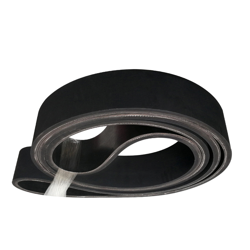
Das Förderband besteht aus Oberflächenkleber, Kern und Schichtkleber. Darüber hinaus kann bei Verwendung von High-Drop-Impact eine Schicht Puffertuch hinzugefügt werden, um die Schlagfestigkeit zu erhöhen.
Der Oberflächenkleber
Mit Naturkautschuk und Synthesekautschuk als Rohstoffen und um die Verschleißfestigkeit, Rissbeständigkeit, Alterungsbeständigkeit und andere Eigenschaften zu verbessern, weist der Oberflächenklebstoff verschiedene Eigenschaften wie Verschleißfestigkeit, Schnittfestigkeit, Hitzebeständigkeit, Flammbeständigkeit, Kältebeständigkeit auf. Säure- und Alkalibeständigkeit, Ölbeständigkeit, Beständigkeit gegen statische Elektrizität usw. Stoffschichtkern
Die Stoffschicht besteht aus Naturfasern oder Chemiefasern allein oder einer Kombination aus beiden, weist nach der einstufigen Behandlung durch einen ausgereiften Prozess die gleiche Qualität auf und weist eine gute Haftung auf Gummi auf. Die Klebeschicht
Die Klebeschicht ist für die Haftkraft zwischen den Schichten des Kerns des Förderbandes, der wiederholt gebogen wird, von großer Bedeutung. Insbesondere bei Fördergurten mit hoher Spannung muss eine Klebstoffschicht mit geringerer Knickspannung und geringerer Ermüdung durch Eigenspannung verwendet werden.
Spezifikationen und Modelle können je nach Kundenwunsch angepasst werden, mit einer Dicke von 2,0 mm bis 8,0 mm.
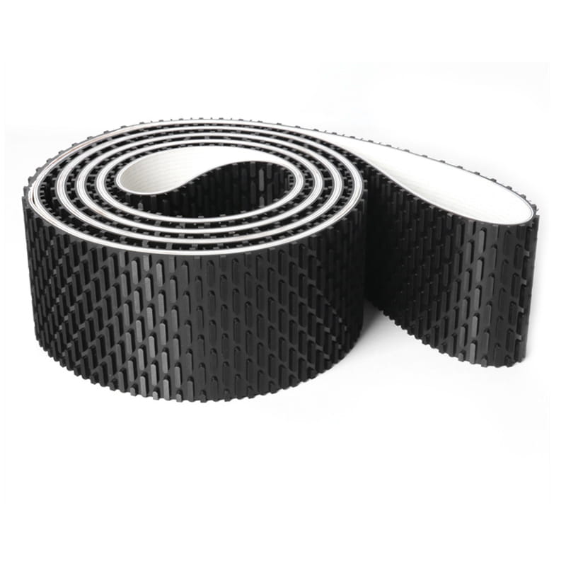
Hochgeschwindigkeits-, sanfte und geringe Dehnungsübertragungs- und Fördersysteme, wie Textilmaschinen, Holzbearbeitungsmaschinen, Schleifmaschinen, Fahrkartenautomaten, Gemüseschneidemaschinen usw. Eigenschaften: Hohe Geschwindigkeit und Stabilität, hohe Zugfestigkeit und geringe Dehnung.
Das von Holzbearbeitungsmaschinen hergestellte nahtlose Gummiband kann zum Schleifen, Korrigieren und Trimmen von Kernmaterialien, zum Hobeln von Holzbrettern, laminierten Brettern, kunststofflaminierten Brettern und anderen Maschinen verwendet werden und kann dazu beitragen, dass die Oberfläche perfekt bearbeitet und ausgewählt wird.
Seine besondere Technologie liegt in der Herstellungsmethode und produziert fugenlose Riemen in der erforderlichen Größe. Wir kontrollieren nicht nur streng die Qualität, sondern bestehen auch auf die Verwendung importierter Materialien, um die Leistung unseres Schleifbandes zu verbessern.
Alle Teile sind in Dicke und Festigkeit absolut gleichmäßig.
Es hat einen guten linearen Betrieb.
Bei kleinen Raddurchmessern kann eine hohe Flexibilität genutzt werden.
Es kann unter Arbeitsdruck die Ebenheit und Nichtverformbarkeit aufrechterhalten.
Der Reibungskoeffizient zwischen der Unterseite des Bandes und der Plattenoberfläche ist sehr niedrig.
Da die Oberflächenschicht des Bandes mit Gummi bedeckt ist, wird die Haftung verbessert und die Stabilität des Förderbandes verbessert.
Auf jedes Feld des synchron angetriebenen Gerätesystems anwenden. Eigenschaften:
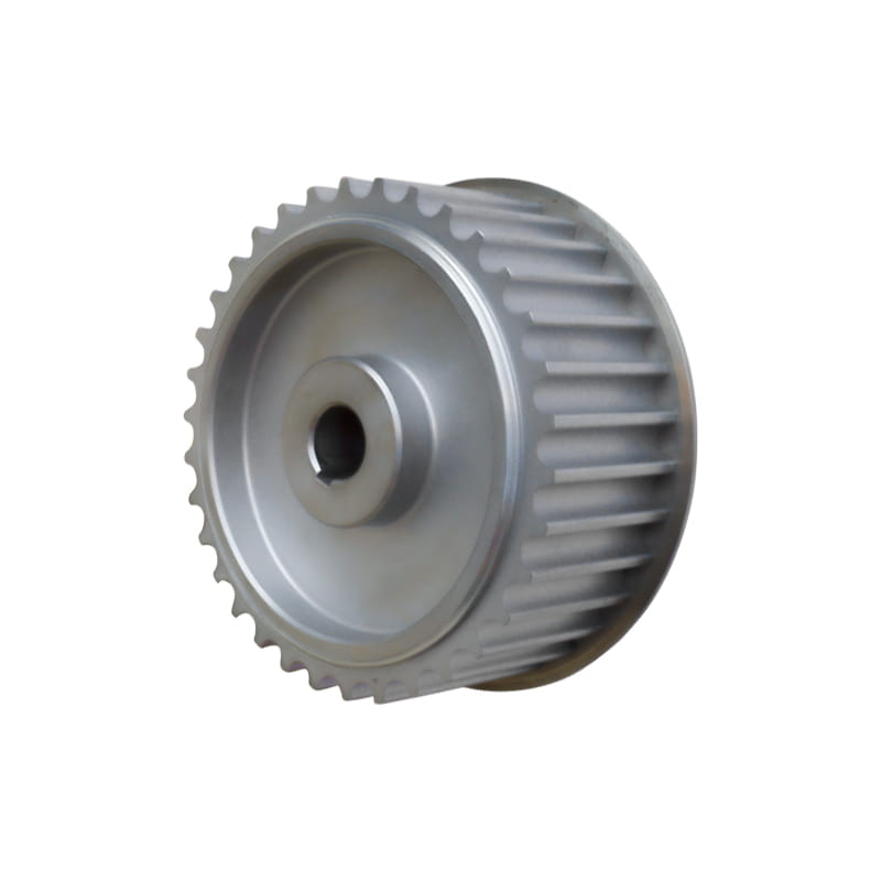
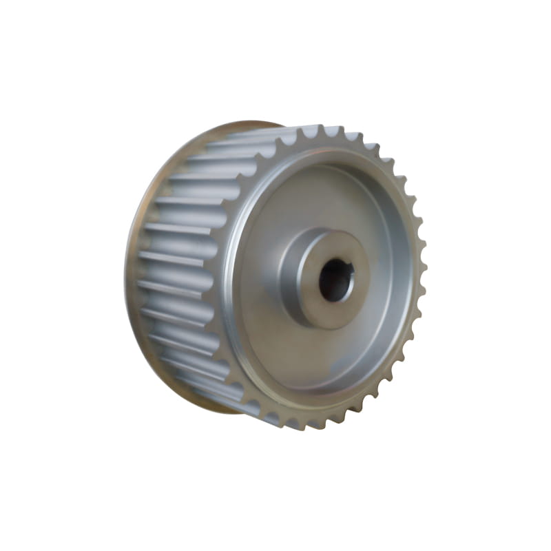
Stellen Sie die Abstimmung mit dem Riemen sicher, um die Genauigkeit und Lebensdauer des Antriebs zu erhöhen. Je nach Kundenwunsch kann die individuell angepasste, optimal gesteuerte Lösung je nach Material in 45#-Stahl, Aluminiumlegierung, Edelstahl, Gusseisen, Nylon usw. unterteilt werden.
Es eignet sich für Übertragungsgeräte im Freien, Transportgeräte, medizinische Geräte, Elektrowerkzeuge, Haushaltsgeräte und Sportgeräte. Eigenschaften:
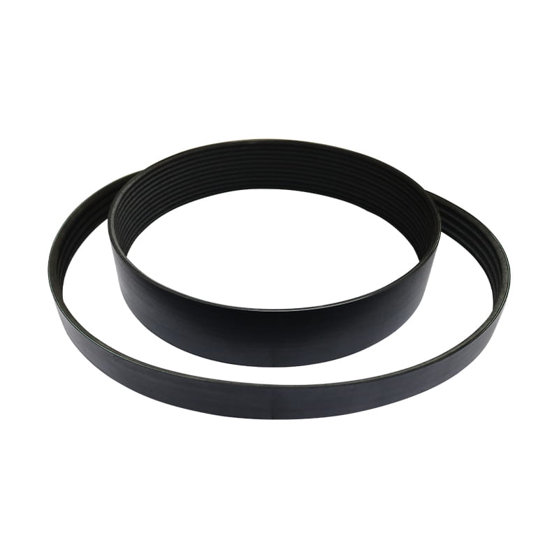
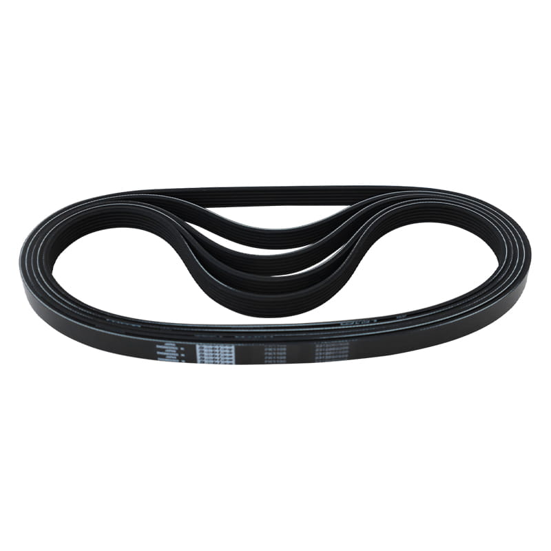
1. Die Übertragungsleistung des Rippenriemens ist bei gleichem Bauraum um 30 % höher als die eines gewöhnlichen Keilriemens.
2. Das Übertragungssystem des Rippenriemens hat eine kompakte Struktur und bei gleicher Übertragungsleistung nimmt der Platz ein
Die Übertragungsvorrichtung ist 25 % kleiner als die des herkömmlichen Keilriemens.
3. Der Rippenriemen ist dünn und flexibel und eignet sich für die Übertragung mit kleinem Riemenscheibendurchmesser und die Hochgeschwindigkeitsübertragung mit Riemen
Geschwindigkeit bis zu 40 m/s; Geringe Vibration, weniger Hitze und stabiler Betrieb.
4. Der Rippenriemen ist hitzebeständig, ölbeständig und verschleißfest, mit geringer Dehnung und langer Lebensdauer.